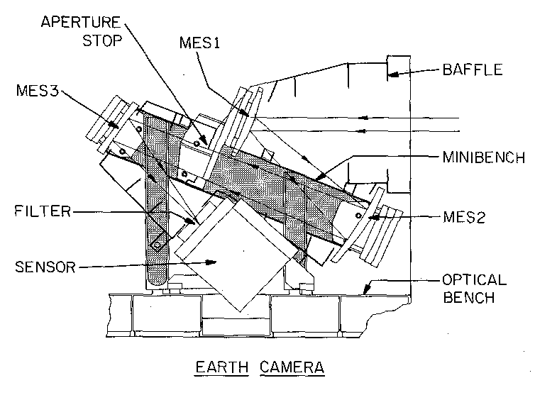
The optics of the Earth camera consists of three off-axis mirrors. This design is based upon a similar camera previously described by Hallam et al. [1983]. The present optics provides a speed of f/4.6 with an entrance pupil diameter of 0.85 cm. A diagram of the mechanical configuration of the Earth sensor is shown in Figure 5. A list of the mirror parameters is given in Table 4. The image at the sensor is provided by a convex spherical mirror MES1, an offaxis parabolic mirror MES2 and a concave spherical mirror MES3, in order of their appearance along the optical path. An ultraviolet transmission interference filter with peak transmission at 130 nm is placed in front of the sensor. The half-maximum full-width of the passband is 25 nm.
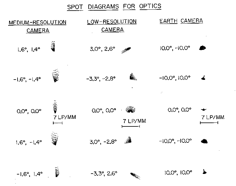
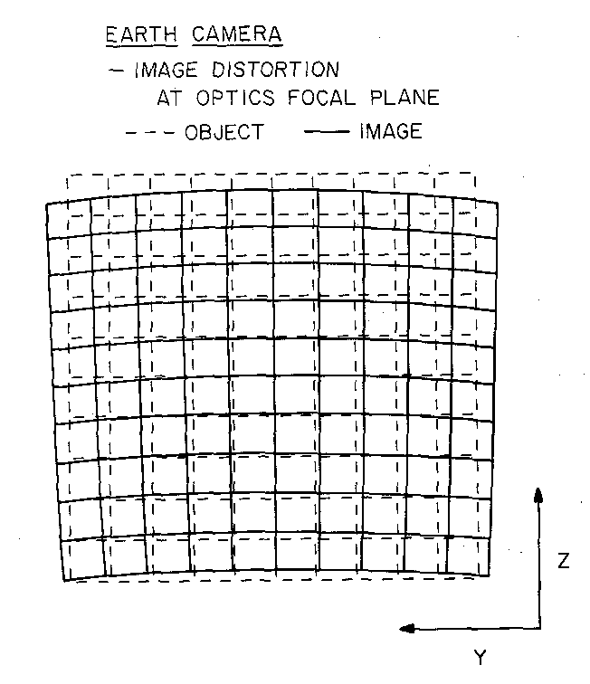
The field-of-view of the Earth camera is 20° × 20°. For reference the full angle of Earth as seen from an altitude of 8 Re is 12.8°. The angular resolution of the optics is shown in the Figure 4. These spot distributions are shown for the four corners and the center of the field-of-view. The linear dimension for two pixels, in the 256 ×256-pixel format, at the sensor input image plane is shown for comparison. The distortion of the image is to be removed with ground processing of the image. This primarily barrel distortion is minimal for the large field-of-view of the camera and is displayed in Figure 6. The MTF of the optics of the Earth camera is given in Table 3. In the 256 ×256-pixel format the corresponding spatial frequency is 7 line pairs/mm. The MTF at 7 line pairs/mm is 0.96.
The mirrors for the Earth camera are constructed from a beryllium
substrate with a superpolished electroless nickel coating and a final
overcoat of MgF2. The mirror figure is  /8 peak-to-peak at visible wavelengths. The
optical elements are mounted on a beryllium optical minibench. The
optical axis of the Earth camera is co-aligned with that of the
collimator for the cameras for visible wavelengths. Stray light
scattering is suppressed to negligible values by the off-axis optical
elements, super-polished mirror surfaces, transmission filter with
aluminum flashing, baffled collimator, and internal baffles. The stray
light intensity is significantly lesser than that for the visible cameras
because the far-ultraviolet intensities from sunlit Earth are generally
greater by factors of only about 1000 or less than those from a dim
nightside aurora.
/8 peak-to-peak at visible wavelengths. The
optical elements are mounted on a beryllium optical minibench. The
optical axis of the Earth camera is co-aligned with that of the
collimator for the cameras for visible wavelengths. Stray light
scattering is suppressed to negligible values by the off-axis optical
elements, super-polished mirror surfaces, transmission filter with
aluminum flashing, baffled collimator, and internal baffles. The stray
light intensity is significantly lesser than that for the visible cameras
because the far-ultraviolet intensities from sunlit Earth are generally
greater by factors of only about 1000 or less than those from a dim
nightside aurora.